
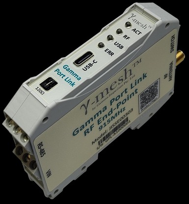
Designed as a radio network access point, either working as a Network Master attached to a controller or as an End Point affixed to a Site Asset, the Gamma Port Link allows remote connectivity of Assets such as Meters and Inverters over long distances without the need for cables. With a key goal of making this device as simple as possible to install and support, the Gamma Port Link requires no device-level configuration, with network connectivity and routing as well as all port-parameters being configured either autonomously or remotely.
Specifications:
a longer range with up to 1000 devices.
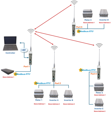
This is the most common configuration, and the most versatile, however it also requires the running of specialty SW to interface the Controller toward the network.
In this configuration, each Remote Device will provide individual access to not only their registers but also their RS-485 ports, which in the above example are used for MODBUS-RTU. Here port slave addressing is only relative to the Port Link port a Site Asset may be connected through, which greatly simplifies installation and allows for a far greater number of Site Assets to be connected through a single Network.
The RS-485 port may also be used by the Master Port Link device in the same way as for remote devices. This configuration may also incorporate other devices such as DCSRs and Environmental Monitor devices (not shown) for HVAC control, which forms a critical part of Demand Response and Load Shifting applications.
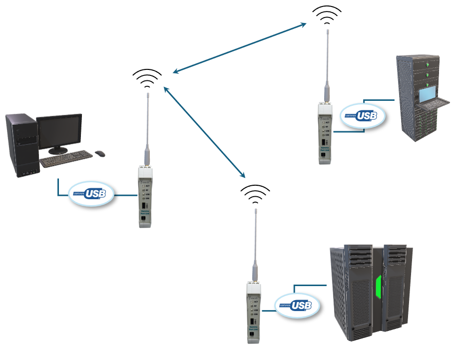
This configuration is a variant of the previous configuration where data is streamed across through to the remote USB port instead of the RS485.
Configuring the Device to operate in this mode can be achieved by following the steps in Section 5.1. Note that for Slave devices the USB data rate is always fixed to 230400 bps, No Parity and One Stop Bit and the packet
data is encoded according to the Gamma Interface requirements.
It should be noted that there is nothing to prevent both these configurations from being used at the same time, as well as interconnecting other device types.
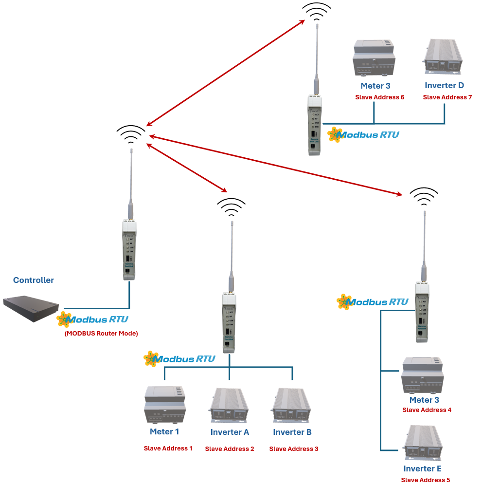
This configuration is typically used when the network is to be used as a simple replacement of long RS-485 cables that may be costly to install and maintain, however the devices that use the connection only support a
MODBUS interface.
In this configuration, the Controller configures the Master Port Link Devices through its RS-485 interface instead of the Gamma Interface. This may be done provided Fall-back packets are not enabled for the device and it has not connected up to a network, in both cases the MODBUS Slave functionality of the device is disabled.
The MODBUS Slave functionality may be enabled by following the instructions in Section 5.2. Please Note: Care must be taken to ensure that all the Site Assets have independent Bus addresses and that only a maximum number of devices are used such as not to violate the MODBUS specifications regarding addressing.